Tutorial
I hope you’re feeling excited and inspired by our adventure writing “Hello World” because we will now walk through a much more substantial project. The goal is to build something that familiarizes you with the multitude of powerful features Monster provides.
By the end of this tutorial we will have a smoothly moving character that can run from side to side and move up and down under joystick control.
Main
This project will span multiple files, but when assembling directly into memory, Monster begins with the
active source file. For us, that will be a MAIN.S file. All other files will be included from
this one (more on that when we get to it).
If you still have buffers open from your past work, close them with  +
+  until only one remains. Press
  to
enter the BUFFERS VIEWER. This will pop open a window which allows you to view all open buffers and
select one to navigate to. Confirm in this view that we have only one buffer open.
to
enter the BUFFERS VIEWER. This will pop open a window which allows you to view all open buffers and
select one to navigate to. Confirm in this view that we have only one buffer open.
Once confirmed, with the BUFFERS VIEWER, press + to close the BUFFERS VIEWER.
You can also press  to re-enter the editor, but leave the viewer onscreen.
We’ll touch more on the concept of these “windows” when we start debugging.
to re-enter the editor, but leave the viewer onscreen.
We’ll touch more on the concept of these “windows” when we start debugging.
Now rename the buffer by entering EX mode ( ) and typing
 r MAIN.S at the prompt.
Let’s set the origin of this program to $2000.
.org $2000
$2000 is outside of the range visible to the VIC, so it is a good location for code on
a program targeting an expanded RAM configuration. Our program will use almost all of the memory
from $1000-$2000, so this is important.
Since this program will be a bit more substantial, we will want to leverage Monster’s macro
capabilities a bit. A good organizational practice for this is to have a single “macros” file
that you include at the top of your “main” assembly file (MAIN.S for us).
To create a new buffer, press +  . This will open a new unnamed buffer. Press
and you should see there are now two buffers:
. This will open a new unnamed buffer. Press
and you should see there are now two buffers: MAIN.S and our new unnamed one.
Macros
Let’s call this new file MACROS.INC. Rename it using the r EX command.
The .inc suffix tells us this is an include file.
Monster doesn’t care what suffix you use in most cases, but avoid .o, which is
reserved for use by the linker.
Note that filenames inside quotes are case-sensitive, so the name in an .inc directive must use exactly the
same case as the file on disk.
On the VIC-20, lowercase PETSCII codes may also appear as graphic characters in a directory listing, which makes uppercase filenames much easier to recognize.
Macro use is very much a matter of personal taste. I avoid heavy macro use as it can obscure potential optimizations, which is half the fun of writing assembly by hand, but there are some simple ones that make life a little bit easier without hiding much from the user.
For this project, we’ll define two macros to treat the index registers X and Y like a single
16-bit value:
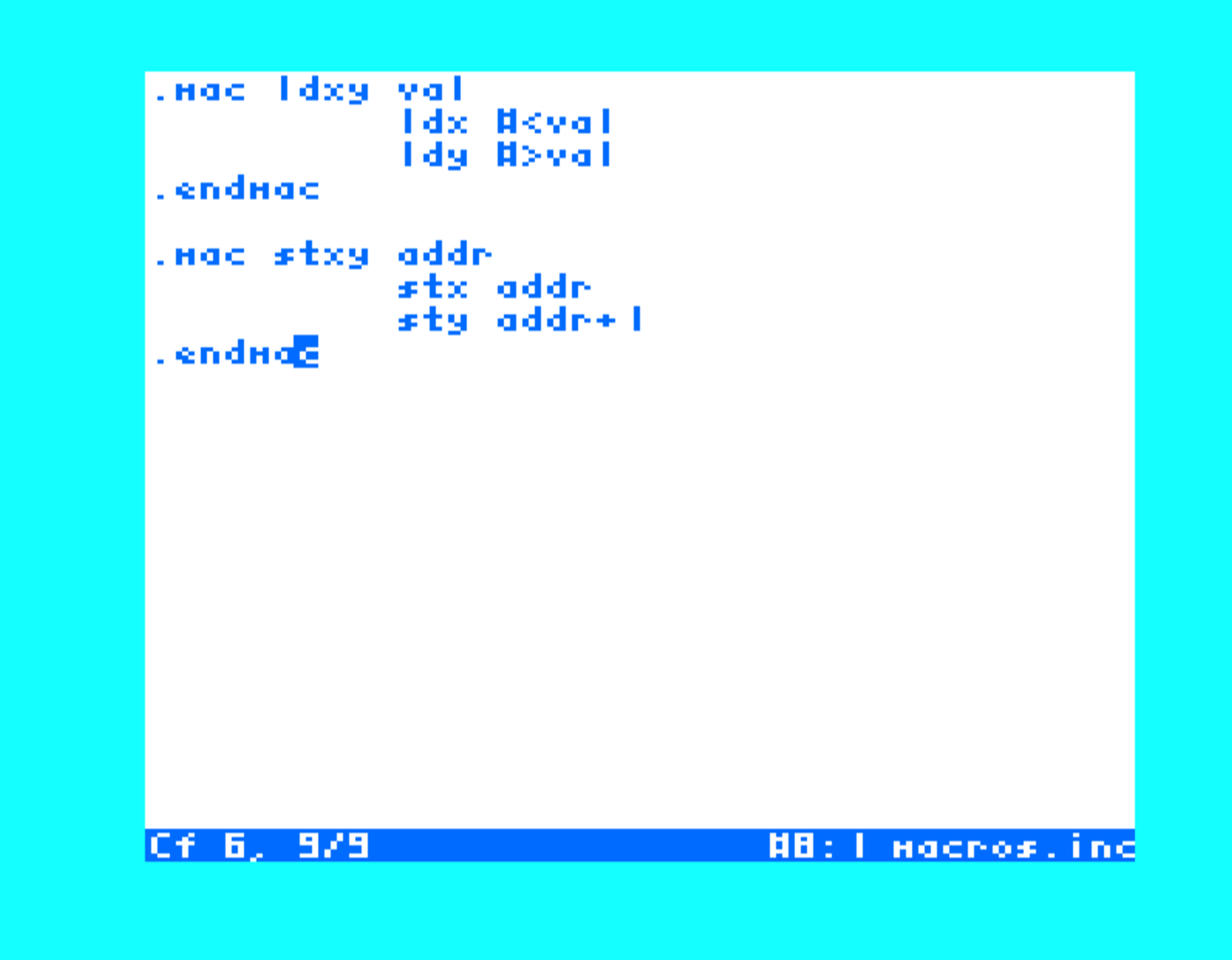
MACROS.INC
By now, hopefully, you’re getting a sense of Monster’s autoformatting and syntax checking.
If you had an error when entering any of the above text, Monster reports it and leaves you on
the line containing the error so that you can correct it. If you made no errors (yet), try
editing .endmac to .endmacc and pressing  to witness this behavior.
Of course, there are some classes of errors that cannot be checked immediately without assembling. You may find it useful to incrementally test your files as you are working on them. You can do this even with files like this which emit no real bytes. In fact, in the case of macros, it’s often a good idea to do so.
If you left the MACROS.INC buffer, return to it and press +  to assemble it. You
should see a simple “DONE” message. But what actually happened? Press +
to assemble it. You
should see a simple “DONE” message. But what actually happened? Press +  to open
the MACRO VIEWER. Here you will see all the macros that Monster has registered from our
assembly.
to open
the MACRO VIEWER. Here you will see all the macros that Monster has registered from our
assembly.
Why might you want to do this? Consider a macro like this:
.mac lsr2
	lsr
	lsr
.endmac
and an invocation like this:
lsr2
How does Monster know if this is a label or a macro invocation? The answer: unless we’ve assembled the definition already, it doesn’t. Monster will format this as a label for lack of information.
This is why it’s a good idea to start your session by assembling your macros file and to include it at the top of your “main” entrypoint file.
Add that include near the top of MAIN.S, immediately after the .org directive:
.inc "MACROS.INC"
The .inc directive assembles the contents of the target file directly. Macros must
be defined before their first use, so that is a compelling reason for including your
macro definitions this way.
Custom characters
Many sizeable programs will contain a relatively large chunk of data. Logically it makes sense to store this in its own file.
A character set is one popular use case, and this is exactly what we’ll be defining. Defining an entire character set is quite a lot of work, so we’re going to base ours on the VIC-20’s own character set.
To do this we will dip our toes into one of Monster’s powerful utilities: the MONITOR.
Press  to activate the monitor. A window will appear in which text commands
are entered. The character set on which we wish to base our design lives at address
to activate the monitor. A window will appear in which text commands
are entered. The character set on which we wish to base our design lives at address $8000 in
the VIC-20’s ROM. Run the following command to take a peek at the memory there:
m $8000
Pretty neat, but not too helpful in producing a usable character set. A couple of modifications
to our command will change that. First, we must understand the > operator available
in the monitor. When appended to a command, the output from the command will be redirected
to whatever filename follows.
The other thing to understand is that commands like dump take an optional second parameter.
In this case, it defines the address at which to stop dumping memory. This ending address is
exclusive, so $8400 includes all bytes through $83ff. With these things in mind, we can
save the whole range from $8000-$83ff (one of the VIC-20’s character sets) to a file for
our own repurposing.
dump $8000 $8400 > CHARS.S
Exit the monitor now by running the x command:
x
This returns you to the editor. Now open the directory viewer and you should see the file we wrote: CHARS.S.
Navigate to it and press . Once it loads you should see a wall of .db
directives. Remember from our “Hello World” example that these define a list of raw byte values.
Now, move the cursor to any .db row and press +  to bring up the UDG EDITOR.
This will show you an 8×8 representation of the VIC’s interpretation of the character data
represented by the row you activated the editor on.
to bring up the UDG EDITOR.
This will show you an 8×8 representation of the VIC’s interpretation of the character data
represented by the row you activated the editor on.
The selection cursor starts on the top-left pixel and blinks. While it is visible, that corner can look as though the outline is misaligned; when the cursor blinks off after a few seconds, the ordinary outline is visible. This does not change the character data.
Feel free to play around with all the other characters in the set. You can always regenerate
the whole set with the same command we used to get the character set in the first place. To do
so, close the CHARS.S buffer, scratch the existing file with :x CHARS.S, and run the dump
command again.
That is enough for now. We will return to the character set once our program is ready to use it—and once we are feeling sufficiently inspired.
Buffer switching
At this point we have at least three buffers open (perhaps more if you got curious). There are several ways to move between them and this will be a frequent part of our workflow, so it’s worth taking a moment to get a handle on them.
 +
+  navigates to the previous buffer and +
  navigates to the
next one. Go back and forth between your buffers with these keys to get a feel for this.
navigates to the
next one. Go back and forth between your buffers with these keys to get a feel for this.
You may have noticed a number to the left of your buffers’ names. This is the buffer’s “ID” but,
more importantly, it is a handle for quick navigation to it. If your MAIN.S buffer has ID 1,
for example, you can jump straight to it, no matter which buffer you’re currently on, by
pressing +  .
.
The last way is one we’ve already seen: the buffer viewer. This is
the most general way to select the buffer you want by name. If you haven’t noticed by now,
the H, J, K, and L keys are almost always usable in addition to the cursor keys. This is
true in the buffer viewer as well as the UDG editor and others we’ve yet to explore.
Implementation logic
Okay, time for the exciting stuff: let’s work on writing the logic that ties everything together.
Navigate to the MAIN.S buffer.
First things first, we need to set up the display. The VIC registers at $9000 retain their “cold start” defaults in Monster’s virtual memory upon boot, but those are not fit for our purposes. Configuring the display can be thought of in two parts: the geometry/attributes, and the matrix.
Let’s begin with geometry and attributes. This is configured by writing to the VIC registers to achieve the desired number of rows/columns, colors, etc. For our program, we will use a matrix that is 12x20 with double height characters. This arrangement allows us to create a large “bitmap” which only uses a single page of memory for the screen matrix (each matrix position representing 16 bytes thanks to the double height characters). This setup is commonly referred to as MINIGRAFIK.
We will first configure the screen’s width and height. Note that in $9003, bit 0 sets double-height
characters and bits 1-6 sets the number of character rows. While we’re here, we might as well set the
color of the border and background too ($900f). Note that bit 3 must be set for non-reverse
colors.
    lda #20        ; # columns
    sta $9002

    lda #(12*2)+1  ; double # rows, then set bit 0
    sta $9003

    lda #$08       ; black/black (no rvs)
    sta $900f

    lda #$cc
    sta $9005	   ; scr+chars @ $1000
Great, now we need to configure the screen matrix. As we alluded to earlier, we want to set up a sort of virtual bitmap, where each column represents one continuous row of bytes. With this arrangement, we can easily address a given pixel by loading a zero page variable with the address of the “sprite“‘s x-position and then using indirect, y-indexed addressing to specify its y-position, e.g.
    ldy spritey
    sta (@col),y
To accomplish this, we must arrange the screen matrix, which is organized row-by-row, so that the values in each row sequentially align with the ones on the row above, e.g.
0 3 6
1 4 7
2 5 8
We will accomplish this with a nested loop that initializes the screen matrix row-by-row.
init
    .eq @addr $f0

    ; set @addr to matrix origin ($1000)
    ldxy $1000
    stxy @addr

    ldx #$10	; screen code
@l0 ldy #0
    txa
:   sta (@addr),y
    clc
    adc #$0c
    iny
    cpy #20
    bne -

    ; next row
    lda @addr
    clc
    adc #20
    sta @addr
    bcc +
    inc @addr+1
:   inx
    cpx #12+$10
    bne @l0
X contains the screen code in this loop. Note that it starts at $10. Our matrix
occupies 20*12 (240) bytes, from $1000 through $10ef. We leave another 16 bytes unused
so the bitmap begins at $1100, corresponding to screen code $10 for double-height characters.
For each column we write, we are updating the screen code by $0c. This is simply the
number of rows in our matrix. Striding by this amount and incrementing our base value per
row gives us a neat arrangement of 1,2,3,4 in the vertical/columnar direction, which is precisely
what we want for easy addressing.
The matrix should now be established. It lives at address $1000 and references a custom
character set from $1100-$1fff (our “bitmap”). At this point, the contents of the bitmap
are yet uninitialized. If we ran the program now, we’d see garbage strewn throughout the
display. Let’s fix that by clearing the bitmap:
clr
.eq @bm $f0
    ldxy $1100
    stxy @bm

    lda #$00
    ldy #$00
    ldx #$20-$11    ; # of pages to clear
:   sta (@bm),y
    iny
    bne -
    inc @bm+1
    dex
    bne -
To clear the full bitmap, we must clear all pages from $1100-$2000. X is our “page counter”,
so we initialize it with the difference of the high bytes of those two addresses. A is zero
to clear every pixel (a 0 means the pixel is unset).
The color memory also needs to be initialized. Color memory corresponds to the screen matrix, and the position
of it depends on the position of the screen matrix. With the matrix at address $1000, the color
memory is located at $9400.
We will clear each cell to white ($01).
    lda #$01
clrcolor
    sta $9400,x
    dex
    bne clrcolor
Color memory also follows the double height character flag, so initializing a single page will handle the entire screen.
We’ve already built a few logical chunks of code. It’s always a good idea to test as you go so that you’re not left trying to hunt down a bug in hundreds of lines of untested code. Let’s take a pause here and familiarize ourselves with the environment a bit more. There’s plenty more of our program to write, but it will help if we can iteratively build up to the final product.
Saving
Before we even think about beginning debugging, we should make sure our progress is safely stored on disk.
You should have a rough handle on saving buffers already (and the importance of doing so). It is always a good idea to save your work before assembling. If you have any dirty buffers, you will be asked if you want to do so with a prompt.
You can also use the EX command :S to save all buffers. The @ suffix can be applied
to all save commands (s and S) to overwrite files that already share the buffers’ names.
In most cases this will be the desired command (save everything and overwrite) and it is
also what will effectively be executed if you confirm “yes” to the prompt you’re given
upon assembly:
Warning
:S@ deletes each existing file before writing its replacement. If a save
fails, that file may be left without its original or a complete replacement.
:S@
Assembly
As mentioned earlier, assembly will typically take place from the top-level unit from which
all others are included (MAIN.S in our case). Navigate to that buffer and press
+ to assemble it.
Errors
There’s a good chance your first assembly will generate one or more errors.
If it does, they are displayed in a menu,
which is focused to allow you to select one for inspection. Press to
navigate to the error you wish to address. This will jump the cursor to the
file/line of the error so that you can fix it.
When you’re satisfied you’ve fixed the error, press +  to navigate to the
next error or press +
to navigate to the
next error or press +  to return to the error menu (this is how you re-enter any “window”
generally). Repeat as needed until you think your program will assemble successfully. And
then repeat as needed until it actually does.
to return to the error menu (this is how you re-enter any “window”
generally). Repeat as needed until you think your program will assemble successfully. And
then repeat as needed until it actually does.
Errors often have a cascading effect, so it’s usually best to address the errors that occurred first during assembly.
Log
In addition to the error window, the log provides a chronological record of what happened during assembly. It will show you the order in which files were processed, errors as they occurred, etc. When your program is successfully assembled, it will also give you details about the final result.
Debugging
This debug session will be more involved than the “Hello World” one. We will cover breakpoints, watches, and the monitor interface (which we’ve already touched on a bit).
As before, press +  to begin the debug session.
Our program begins by configuring the screen layout. To sanity check that this looks as expected,
let’s just step through all of that. Press  several times until the cursor is
past all the VIC writes (stores to
several times until the cursor is
past all the VIC writes (stores to $90xx). Then press  to observe the new state of
the screen post-setup.
to observe the new state of
the screen post-setup.
Alternatively, you can set a breakpoint after all the setup code and use either TRACE
( ) or GO ( +
  ) to run to it. Both stop at the breakpoint;
TRACE simulates each instruction and displays the program screen as it progresses, while
GO gives control directly to the program and runs it in realtime. But be careful: a
) to run to it. Both stop at the breakpoint;
TRACE simulates each instruction and displays the program screen as it progresses, while
GO gives control directly to the program and runs it in realtime. But be careful: a JAM,
if encountered, will require you to reset the machine. Another reason to save often.
So far so good? If not, you may want to enter the monitor () to make sure the VIC registers are configured
as expected:
m $9000 $9010
Our setup code is very simple, so if any correction is required it ought to be a simple exercise from here.
Remember, if you need to edit your program at any point during the debug cycle, you must first
stop debugging ( +  ) to return to edit mode. Breakpoint toggles are the exception:
you may add or remove them from the debugger. When you are done with ordinary source changes,
reassemble the program ( + ) and try again.
) to return to edit mode. Breakpoint toggles are the exception:
you may add or remove them from the debugger. When you are done with ordinary source changes,
reassemble the program ( + ) and try again.
Okay, however circuitous your path to get there, let’s continue our debug session post-VIC initialization. This is where the code gets a bit more interesting. For starters, we have control flow to initialize the screen. And it’s quite a lot of iterations this time. Repeated stepping would be tedious here, so let’s instead set a breakpoint after the screen initialization loop and see if the outcome is as we expect.
While still in the debugger, move the cursor to ldxy $1100, the first instruction below the
clr label, and press +  . The breakpoint marker appears on that line. Breakpoints
can be added while debugging and take effect immediately, so you do not need to quit or reassemble.
Now press + to run. Monster returns to the debugger when execution reaches
. The breakpoint marker appears on that line. Breakpoints
can be added while debugging and take effect immediately, so you do not need to quit or reassemble.
Now press + to run. Monster returns to the debugger when execution reaches
ldxy $1100; at that point the loop above it has initialized the complete screen matrix.
The easiest way to inspect the output here is a tool we’ve yet to invoke: the MEMORY VIEWER (activated
with  ). The memory viewer is similar to the monitor’s
 m command, but it allows us to easily
scroll around through memory as we please using the usual motion keys (h/j/k/l).
Once activated, set the address to our screen matrix by pressing the dedicated  key—not the cursor-up key—and then entering
 1000 and
. The viewer will refresh with the contents at address $1000 and hopefully you will
see a steadily increasing (by $0c) array of values: 10, 1c, 28, …
If you don’t, then try to see what is wrong with the pattern, hunt for any bugs in the initialization loop, and fix using the usual flow.
Window management
We introduced the concept of windows earlier with the BUFFER VIEWER. The MEMORY VIEWER is another one. A WINDOW is an interactive widget that can be invoked to allow you to view breakpoints and watches, enter the monitor, and perform similar tasks.
While these behave totally differently than the BUFFER VIEWER, they all share some common functionality.
To control the window’s geometry, press +  / +
/ +  to resize (shrink/grow),
or + to maximize/unmaximize
+ closes the active window, and leaves the selected window (without
closing it) and refocuses the editor.
to resize (shrink/grow),
or + to maximize/unmaximize
+ closes the active window, and leaves the selected window (without
closing it) and refocuses the editor.
Note that multiple windows may be open at once. If the MEMORY VIEWER is active, you may still invoke
the BREAKPOINT VIEWER without closing it. If multiple windows are active, you can cycle through them
with + (also re-enters the visible window if the editor is in focus).
Finally, all active windows can be hidden with + . Repeating the command also unhides
them if they are already hidden.
Editor tips
Before we finish up our program, let’s take a moment to hone our editing skills.
The MAIN.S buffer is still small, but it’s getting big enough that navigation by individual cursor
motion may be feeling a little cumbersome. Fortunately Monster has many options for zipping around your
code more efficiently. We will touch on only a few here.
To go to the top of the buffer, press . Note that this command (and some others)
waits for a second keypress (the second G in this case). You can see the buffered input in
the status bar when another key is expected.
To go to the bottom of the buffer, press  + .
+ .
Press  to open a FIND prompt. At the prompt, enter the string to look for, then
press . Press to navigate to the next occurrence of the string
(assuming one is found) or + to navigate to the previous one.
to open a FIND prompt. At the prompt, enter the string to look for, then
press . Press to navigate to the next occurrence of the string
(assuming one is found) or + to navigate to the previous one.
Press  and
and  to navigate to the previous and next empty lines, respectively.
Empty lines therefore make useful logical divisions in your source.
to navigate to the previous and next empty lines, respectively.
Empty lines therefore make useful logical divisions in your source.
Banner comments are also common practice to separate logical blocks of procedures or data. Monster
also allows to easily navigate to these with + (previous banner) and +  (next banner).
Finally, a common practice will be inserting new lines above or below the current line.
From command mode you can do this by pressing  (to insert a line below) or +
to insert one above the current line. Both commands will also enter insert mode so that you can
immediately begin writing your new line.
(to insert a line below) or +
to insert one above the current line. Both commands will also enter insert mode so that you can
immediately begin writing your new line.
This should get you started. See the EDITOR chapter for the other navigation commands if you still find yourself frustrated at your editing/navigation speed.
Finishing the program
We’re not quite done with initialization just yet. Remember that we wish to use joystick input to move the player sprite around the screen. To do this we need to configure the VIAs (the VIC-20’s chips responsible for handling keyboard/joystick input, among other duties) to read the joystick. This is almost as simple as our VIC initialization was.
The lines to the joystick are not wired to a single port. UP, DOWN, LEFT and FIRE are wired
to port A ($9111) on VIA #1. However, the RIGHT direction is wired to bit 7 of VIA #2 port B ($9120).
The switches read active low, so a 0 bit means that the switch is closed in the direction being pushed/pressed.
Direction |
Register |
Bit |
|---|---|---|
up |
|
2 ( |
down |
|
3 ( |
left |
|
4 ( |
fire |
|
5 ( |
right |
|
7 ( |
Only the VIA #1 lines need to be configured up front. We do that by clearing bits 2-5 of the
data direction register at $9113 to mark those pins as inputs. Note that we mask the
existing value instead of simply storing one: bit 7 of this port is the serial bus ATN line
(an output), and we would break disk access if we clobbered it.
    ; VIA1 PA2-PA5 (up/down/left/fire) -> inputs
    lda $9113
    and #$c3      ; %11000011: clear bits 2-5, leave the rest alone
    sta $9113
There is deliberately nothing here for the “right” switch. VIA #2’s port B is the keyboard
column drive, so its data direction register ($9122) is set to all-outputs by the KERNAL.
We will borrow bit 7 of it for a few cycles at a time when we read the joystick, then hand it
straight back.
There’s a few remaining items to finish up the program.
redraw the sprite at its new position
read input from the joystick
apply the input to the “player” sprite position
Let’s start with #1 so that we can see our sprite at all before we worry about moving it.
Sprite Rendering
There are various ways to render a sprite. For this tutorial we will use a rather crude approach, but you may experiment with optimizations to speed it up.
The concept is this: the VIC-20 has only rough 8x8 character positions in hardware. In software, however, we can leverage the bitmap that we have already configured to move a sprite smoothly (pixel-by-pixel). To do this, we shift the sprite data by the number of pixels that it is offset from the nearest character boundary (0-7). At the character boundary, we move it to the next 8-pixel wide cell.
We will move the sprite one bitmap bit at a time. Its spritex position therefore also tells
us how many places to shift it within the current character cell.
The spillover that is shifted out of the character “sprite” will be rotated into the next character to the right.
Okay, here’s the code to do the sprite shift.
drawspr
    ldx #7
@l0 lda #$00
    sta sprite+8,x
    lda spritedat,x
    sta sprite,x
    lda spritex
    and #$07
    tay
    beq @cont

    lda spritedat,x
:   lsr
    ror sprite+8,x
    dey
    bne -
    sta sprite,x

@cont
    dex
    bpl @l0
Here sprite contains 16 bytes of data. sprite contains the left half and sprite+8 the right
one. When spritex evenly divides by 8, we skip the shift altogether (this is the beq @cont after
we initialize the sprite data for the row).
We’ve now copied the shifted sprite into a 16-byte buffer. All that’s left to get the sprite on screen is to copy this buffer onto our software-defined bitmap. You may have wondered why we haven’t considered the sprite’s y-position at all. Remember that our bitmap is organized in linear columns of pixels. To draw to any arbitrary y-position we just need to offset our write to the correct column by the sprite’s y-position.
To make the addressing even easier we will define a pair of tables using the .REP directive:
columnslo
.rep 20,i
    .db <($1100+(i*$c0))
.endrep

columnshi
.rep 20,i
    .db >($1100+(i*$c0))
.endrep
We could also use a word-sized table, but splitting the table into two parallel tables for the least and most significant bytes will make addressing easier. This is a common technique.
Now, picking up where we left off our draw procedure. We will first use our column tables to get the
address of the first column (x/8). If spritex & 7 is nonzero, the sprite overflows into
a second column (x/8+1), so we look up that address too.
When the sprite is aligned, we skip the second-column lookup and writes. This also prevents us from reading an invalid column when the sprite is at its rightmost position.
Once we have our column addresses the only thing to do is to perform the blit from our buffered shifted sprite data.
.eq @col $f0
.eq @col2 $f2

    ; get column address (x/8)
    lda spritex
    lsr
    lsr
    lsr
    tax
    lda columnslo,x
    sta @col
    lda columnshi,x
    sta @col+1
    lda spritex
    and #$07
    beq @draw
    lda columnslo+1,x
    sta @col2
    lda columnshi+1,x
    sta @col2+1

@draw
    ldy spritey
    ldx #7
@blit
    lda sprite,x
    sta (@col),y
    lda spritex
    and #$07
    beq @rowdone
    lda sprite+8,x
    sta (@col2),y
@rowdone
    dey
    dex
    bpl @blit

    rts
We prefer to use Y here as the destination offset in the bitmap because it allows
us to use indirect y-indexed addressing. The X register is often less versatile when
this sort of addressing is needed, so we use it as a basic counter for the number of rows
being “blitted”.
We should verify that this works as expected before continuing, so let’s add a call to drawspr
to our main loop. For now, we’ll just call it again and again.
main
    jsr drawspr
    jmp main
We also need to define all the new sprite we are drawing and its associated state
spritedat
.db $ff,$ff,$ff,$ff,$ff,$ff,$ff,$ff
sprite
    .res 16
spritex
    .db 0
spritey
    .db 120
As we mentioned earlier, sprite is 16 bytes (double the size of the sprite data). sprite+8
contains the overflow when the sprite is shifted to the right.
spritey is the bottom-row coordinate of the eight-pixel-high sprite. It is initialized
here as 120, so the sprite occupies rows 113–120 of the bitmap.
Save your work and assemble. Fix any bugs/typos and continue on to debugging. Step/trace however you like and hopefully you should see the new sprite visible on screen by the time we get through one iteration of the main loop.
Beautiful work. Now it’s time to actually move the sprite.
Reading the joystick
We configured VIA #1 back in our init routine, so four of the five switches are ready to read.
We can define constants for each direction to make our code a bit more legible.
.eq JOYUP    $04
.eq JOYDOWN  $08
.eq JOYLEFT  $10
.eq JOYFIRE  $20
.eq JOYRIGHT $80
Now to perform the read itself. Recalling that 4 of the 5 joystick lines are wired to VIA #1, let’s first poll it to see if any of those are pressed.
We will EOR the value by $ff so that the active low values become 1 and then mask all irrelevant
data from the port register by doing an AND with all the “don’t care” bits set to 0.
readjoy
    lda $9111      ; up/down/left/fire
    eor #$ff       ; active low -> active high
    and #$3c       ; keep only bits 2-5
    sta joy
That leaves “right”. As we noted earlier, it shares a pin with the keyboard column drive, so we briefly make PB7 an input, sample it, and then restore the port to all-outputs.
Our program doesn’t need the keyboard, so you could simply keep PB7 as an input forever, but this approach allows you to extend the program with keyboard input later if you wish.
    sei
    lda #$7f
    sta $9122      ; PB7=input
    lda $9120      ; sample
    ldx #$ff
    stx $9122      ; PB7=output (restore keyboard)
    cli

    eor #$ff       ; active low -> active high
    and #JOYRIGHT
    ora joy
    sta joy
    rts
Now our joy variable contains the current state of each switch in the joystick, 1 bit
per switch.
7 |
6 |
5 |
4 |
3 |
2 |
1 |
0 |
|---|---|---|---|---|---|---|---|
right |
fire |
left |
down |
up |
Note that we disabled interrupts when sampling the joystick. The KERNAL
IRQ is still enabled in our program, and it uses the VIA for keyboard input.
Without this, the KERNAL may read bad data, thinking the VIAs are still in the state
it left them. We restore $9122 to the KERNAL’s usual value to keep things in
the state it expects.
With the switches in joy, moving the player is just a matter of looking at this variable
and applying the appropriate INC or DEC.
We will also clamp the sprite position to prevent it from leaving the bitmap range.
Since spritey is the bottom-row coordinate, its valid range is 7–191 ($07–$bf)
within the 192-pixel-high bitmap.
movespr
    lda joy
    and #JOYLEFT
    beq +
    lda spritex
    beq +          ; already at the left edge
    dec spritex

:   lda joy
    and #JOYRIGHT
    beq +
    lda spritex
    cmp #(20*8)-8
    beq +
    inc spritex

:   lda joy
    and #JOYUP
    beq +
    lda spritey
    cmp #7
    beq +
    dec spritey

:   lda joy
    and #JOYDOWN
    beq +
    lda spritey
    cmp #$c0-1
    beq +
    inc spritey

:   rts
And the new state that these routines need:
joy
    .db 0
Finally, wire it all into the main loop. Draw the initial sprite once, then wait for a
stable raster position before erasing the old image (by polling $9004), updating its position,
and redrawing it:
    jsr drawspr
main
    lda #$60
:   cmp $9004
    bne -
    jsr drawspr     ; erase
    jsr readjoy
    jsr movespr
    jsr drawspr     ; redraw
    jmp main
Polling $9004 is a common, basic way to introduce a predictable delay and make sure updates occur
in an area of the display that will not cause “tearing”, visible artifacts as the sprite is erased
and redrawn.
Assemble and run once more.
The sprite should now follow the joystick. So close! But you’ll notice one thing immediately:
the sprite smears as it moves, leaving a trail of itself wherever it goes.
This is because drawspr only ever draws the sprite — we never erase the sprite at its previous position.
Simple enough to fix.
There are two popular approaches to erasing a sprite
saving a “backup” of the data that the sprite is drawing over.
EORing the sprite with itself
The EOR approach is simpler: applying the same sprite mask twice restores the original
background, provided it has not changed between drawing and erasing.
For our purposes (1 sprite, blank background) it is perfect. And it hardly requires any new code.
All we have to do is slightly modify the code that stores the sprite data to the screen. Go back to
your blit loop and add an eor (@col),y between the sprite data loads and the bitmap writes.
@blit
    lda sprite,x
    eor (@col),y	; new
    sta (@col),y
    lda spritex
    and #$07
    beq @rowdone
    lda sprite+8,x
    eor (@col2),y	; new
    sta (@col2),y
@rowdone
    dey
    dex
    bpl @blit
Reassemble and give this updated code another go in the debugger.
When you free run the program, you should now see the sprite moving around cleanly on the screen.
Cycling through the character set
The solid block was a fun start to prove out our sprite renderer works, but what about our character set we worked so hard to rip and edit? Next we will allow the user of our program to access our character set by programmatically changing the sprite data that is rendered.
To accomplish this, let’s replace the hardcoded spritedat with a character ID and include the
entire character set at the end of MAIN.S:
spriteid
    .db 0
swaptmr
    .db 0

sprite
    .res 16
spritex
    .db 0
joy
    .db 0
spritey
    .db 120

chars
    .inc "CHARS.S"
The chars label represents the address of our character set.
If you wish, you may also put the chars label inside the CHARS.S file.
spriteid will represent the cell from our character set that we’ll render. It will
be the basis for the multiplication we do to calculate the actual data for the “sprite” at
runtime.
swaptmr will help us slow down the fire button reads. Without some kind of delay, the
fire button would be polled far too quickly by our program and it would be a chaotic
experience cycling through the character set.
Next, replace the first half of drawspr with code that finds the selected character and
shifts its eight rows into the existing 16-byte sprite buffer:
drawspr
.eq @spr $f0
.eq @next $f2
    ; get sprite data from id
    lda #$00
    sta @spr+1
    lda spriteid
    asl
    rol @spr+1
    asl
    rol @spr+1
    asl
    rol @spr+1
    adc #<chars
    sta @spr
    lda #>chars
    adc @spr+1
    sta @spr+1

    ldy #7
@l0 lda #$00
    sta @next
    lda (@spr),y
    sta sprite,y
    lda spritex
    and #$07
    tax
    beq @cont

    lda (@spr),y
:   lsr
    ror @next
    dex
    bne -
    sta sprite,y

@cont
    lda @next
    sta sprite+8,y
    dey
    bpl @l0
Here we really want to use @spr with indirect, y-indexed addressing, but we also
want to use x-indexed addressing for the ROR into the overflow area of our sprite data.
As a compromise, we define a new zero page scratch variable called @next and ROR into
it per row-iteration.
Now, the updates to our joystick handler movespr.
At the beginning of this procedure, handle the fire button before checking the four directions:
movespr
    lda joy
    and #JOYFIRE
    beq +
    lda swaptmr
    bne +
    inc spriteid
    lda spriteid
    and #$7f
    sta spriteid
    lda #$08
    sta swaptmr
:   lda joy
The existing left-direction code follows immediately after that final lda joy.
The and #$7f wraps spriteid from 127 to 0, keeping it within the 128 character set.
Note that we are checking the swaptmr counter here to stop the handler from changing characters
every single frame. We are reinitializing the delay with $08 each time we cycle characters,
but you may experiment with this value.
Finally, count the repeat timer down once per pass through the main loop:
    jsr drawspr     ; redraw
    lda swaptmr
    beq main
    dec swaptmr
    jmp main
We are careful not to decrement the timer if it’s already 0 here. If we did, the timer would
overflow and we’d have to be very lucky to press the joystick on the exact frame where the timer is 0.
Assemble and run again. Press fire to cycle through the characters in CHARS.S; any changes
you made with the UDG editor should now appear in the moving sprite.
Symbol viewer
It is often useful to examine the symbols defined once your program is assembled. This is
a great way to get a sense of the program’s final layout and make sure things look
as you expect. It’s also useful if you can’t remember the name of one of your symbols
and need a quick refresher. To make inspecting this state easier, Monster has a SYMBOL VIEWER
(activated with +  ). This viewer displays a list of all symbols defined in the
last assembly along with their addresses.
). This viewer displays a list of all symbols defined in the
last assembly along with their addresses.  toggles between name and address
sorting in this view. Press on a symbol to navigate to its
definition.
toggles between name and address
sorting in this view. Press on a symbol to navigate to its
definition.
Where to go from here
What we’ve built here is a great starting point for further experimentation. Try changing the sprite data or adding sound effects when the sprite moves.
The rest of the manual serves as a reference as you continue to advance. It is worth giving a first pass read, but the best way to learn is to keep exercising your abilities by using Monster. Have fun!
Complete program
For reference, here are the complete contents of each source file from the tutorial disk.
MAIN.S
.org $2000

.inc "MACROS.INC"

.eq JOYUP    $04
.eq JOYDOWN  $08
.eq JOYLEFT  $10
.eq JOYFIRE  $20
.eq JOYRIGHT $80

init
	.eq @addr $f0

	; configure MINIGRAFIK
	lda #20        ; # columns
	sta $9002

	lda #(12*2)+1  ; dbl rows
	sta $9003

	lda #$08
	sta $900f

	lda #$cc
	sta $9005

	lda $9113
	and #$c3
	sta $9113

	ldxy $1000
	stxy @addr

	ldx #$10
@l0	ldy #0
	txa
:	sta (@addr),y
	clc
	adc #$0c
	iny
	cpy #20
	bne -

	; next column
	lda @addr
	clc
	adc #20
	sta @addr
	bcc +
	inc @addr+1
:	inx
	cpx #12+$10
	bne @l0

clr
	.eq @bm $f0
	ldxy $1100
	stxy @bm

	lda #$00
	ldy #$00
	ldx #$20-$11
:	sta (@bm),y
	iny
	bne -
	inc @bm+1
	dex
	bne -

	lda #$01
clrcolor
	sta $9400,x
	sta $9500,x
	dex
	bne clrcolor

	jsr drawspr
main	lda #$60
:	cmp $9004
	bne -
	jsr drawspr	; erase
	jsr readjoy
	jsr movespr
	jsr drawspr ; redraw
	lda swaptmr
	beq main
	dec swaptmr
	jmp main

;;;;;;;;;;;;;;;;;;;;;;;;;;;;;;;;;;;;;;;;
drawspr
.eq @spr $f0
.eq @next $f2
; get sprite data from id
	lda #$00
	sta @spr+1
	lda spriteid
	asl
	rol @spr+1
	asl
	rol @spr+1
	asl
	rol @spr+1
	adc #<chars
	sta @spr
	lda #>chars
	adc @spr+1
	sta @spr+1

	ldy #7
@l0	lda #$00
	sta @next
	lda (@spr),y
	sta sprite,y
	lda spritex
	and #$07
	tax
	beq @cont

	lda (@spr),y
:	lsr
	ror @next
	dex
	bne -
	sta sprite,y

@cont	lda @next
	sta sprite+8,y
	dey
	bpl @l0

	.eq @col $f0
	.eq @col2 $f2

; get column address (x/8)
	lda spritex
	lsr
	lsr
	lsr
	tax
	lda columnslo,x
	sta @col
	lda columnshi,x
	sta @col+1
	lda spritex
	and #$07
	beq @draw
	lda columnslo+1,x
	sta @col2
	lda columnshi+1,x
	sta @col2+1

@draw
	ldy spritey
	ldx #7
@blit
	lda sprite,x
	eor (@col),y
	sta (@col),y
	lda spritex
	and #$07
	beq @rowdone
	lda sprite+8,x
	eor (@col2),y
	sta (@col2),y
@rowdone
	dey
	dex
	bpl @blit

	rts

;;;;;;;;;;;;;;;;;;;;;;;;;;;;;;;;;;;;;;;;
readjoy
	lda $9111      ; U/D/L/fire
	eor #$ff
	and #$3c       ; keep bits 2-5
	sta joy

	sei
	lda #$7f
	sta $9122      ; PB7=input
	lda $9120      ; sample
	ldx #$ff
	stx $9122      ; PB7=output
	cli

	eor #$ff
	and #JOYRIGHT
	ora joy
	sta joy
	rts

;;;;;;;;;;;;;;;;;;;;;;;;;;;;;;;;;;;;;;;;
movespr
	lda joy
	and #JOYFIRE
	beq +
	lda swaptmr
	bne +
	inc spriteid
	lda spriteid
	and #$7f
	sta spriteid
	lda #$08
	sta swaptmr
:	lda joy
	and #JOYLEFT
	beq +
	lda spritex
	beq +
;dec spritex
	dec spritex

:	lda joy
	and #JOYRIGHT
	beq +
	lda spritex
	cmp #(20*8)-8
	beq +
;inc spritex
	inc spritex

:	lda joy
	and #JOYUP
	beq +
	lda spritey
	cmp #7
	beq +
	dec spritey

:	lda joy
	and #JOYDOWN
	beq +
	lda spritey
	cmp #$c0-1
	beq +
	inc spritey

:	rts

;;;;;;;;;;;;;;;;;;;;;;;;;;;;;;;;;;;;;;;;
columnslo
.rep 20,i
	.db	<($1100+(i*$c0))
.endrep

columnshi
.rep 20,i
	.db >($1100+(i*$c0))
.endrep

;;;;;;;;;;;;;;;;;;;;;;;;;;;;;;;;;;;;;;;;
spriteid	.db 0
swaptmr	.db 0

sprite	.res 16
spritex	.db 0
joy	.db 0
spritey	.db 120

;;;;;;;;;;;;;;;;;;;;;;;;;;;;;;;;;;;;;;;;
chars
.inc "CHARS.S"
MACROS.INC
.mac ldxy val
    ldx #<val
    ldy #>val
.endmac

.mac stxy addr
    stx addr
    sty addr+1
.endmac
CHARS.S
.db $1c,$22,$4a,$56,$4c,$20,$1e,$00
.db $18,$24,$42,$7e,$42,$42,$42,$00
.db $7c,$22,$22,$3c,$22,$22,$7c,$00
.db $1c,$22,$40,$40,$40,$22,$1c,$00
.db $78,$24,$22,$22,$22,$24,$78,$00
.db $7e,$40,$40,$78,$40,$40,$7e,$00
.db $7e,$40,$40,$78,$40,$40,$40,$00
.db $1c,$22,$40,$4e,$42,$22,$1c,$00
.db $42,$42,$42,$7e,$42,$42,$42,$00
.db $1c,$08,$08,$08,$08,$08,$1c,$00
.db $0e,$04,$04,$04,$04,$44,$38,$00
.db $42,$44,$48,$70,$48,$44,$42,$00
.db $40,$40,$40,$40,$40,$40,$7e,$00
.db $42,$66,$5a,$5a,$42,$42,$42,$00
.db $42,$62,$52,$4a,$46,$42,$42,$00
.db $18,$24,$42,$42,$42,$24,$18,$00
.db $7c,$42,$42,$7c,$40,$40,$40,$00
.db $18,$24,$42,$42,$4a,$24,$1a,$00
.db $7c,$42,$42,$7c,$48,$44,$42,$00
.db $3c,$42,$40,$3c,$02,$42,$3c,$00
.db $3e,$08,$08,$08,$08,$08,$08,$00
.db $42,$42,$42,$42,$42,$42,$3c,$00
.db $42,$42,$42,$24,$24,$18,$18,$00
.db $42,$42,$42,$5a,$5a,$66,$42,$00
.db $42,$42,$24,$18,$24,$42,$42,$00
.db $22,$22,$22,$1c,$08,$08,$08,$00
.db $7e,$02,$04,$18,$20,$40,$7e,$00
.db $3c,$20,$20,$20,$20,$20,$3c,$00
.db $0c,$10,$10,$3c,$10,$70,$6e,$00
.db $3c,$04,$04,$04,$04,$04,$3c,$00
.db $00,$08,$1c,$2a,$08,$08,$08,$08
.db $00,$00,$10,$20,$7f,$20,$10,$00
.db $00,$00,$00,$00,$00,$00,$00,$00
.db $08,$08,$08,$08,$00,$00,$08,$00
.db $24,$24,$24,$00,$00,$00,$00,$00
.db $24,$24,$7e,$24,$7e,$24,$24,$00
.db $08,$1e,$28,$1c,$0a,$3c,$08,$00
.db $00,$62,$64,$08,$10,$26,$46,$00
.db $30,$48,$48,$30,$4a,$44,$3a,$00
.db $04,$08,$10,$00,$00,$00,$00,$00
.db $04,$08,$10,$10,$10,$08,$04,$00
.db $20,$10,$08,$08,$08,$10,$20,$00
.db $08,$2a,$1c,$3e,$1c,$2a,$08,$00
.db $00,$08,$08,$3e,$08,$08,$00,$00
.db $00,$00,$00,$00,$00,$08,$08,$10
.db $00,$00,$00,$7e,$00,$00,$00,$00
.db $00,$00,$00,$00,$00,$18,$18,$00
.db $00,$02,$04,$08,$10,$20,$40,$00
.db $3c,$42,$46,$5a,$62,$42,$3c,$00
.db $08,$18,$28,$08,$08,$08,$3e,$00
.db $3c,$42,$02,$0c,$30,$40,$7e,$00
.db $3c,$42,$02,$1c,$02,$42,$3c,$00
.db $04,$0c,$14,$24,$7e,$04,$04,$00
.db $7e,$40,$78,$04,$02,$44,$38,$00
.db $1c,$20,$40,$7c,$42,$42,$3c,$00
.db $7e,$42,$04,$08,$10,$10,$10,$00
.db $3c,$42,$42,$3c,$42,$42,$3c,$00
.db $3c,$42,$42,$3e,$02,$04,$38,$00
.db $00,$00,$08,$00,$00,$08,$00,$00
.db $00,$00,$08,$00,$00,$08,$08,$10
.db $0e,$18,$30,$60,$30,$18,$0e,$00
.db $00,$00,$7e,$00,$7e,$00,$00,$00
.db $70,$18,$0c,$06,$0c,$18,$70,$00
.db $3c,$42,$02,$0c,$10,$00,$10,$00
.db $00,$00,$00,$00,$ff,$00,$00,$00
.db $08,$1c,$3e,$7f,$7f,$1c,$3e,$00
.db $10,$10,$10,$10,$10,$10,$10,$10
.db $00,$00,$00,$ff,$00,$00,$00,$00
.db $00,$00,$ff,$00,$00,$00,$00,$00
.db $00,$ff,$00,$00,$00,$00,$00,$00
.db $00,$00,$00,$00,$00,$ff,$00,$00
.db $20,$20,$20,$20,$20,$20,$20,$20
.db $04,$04,$04,$04,$04,$04,$04,$04
.db $00,$00,$00,$00,$e0,$10,$08,$08
.db $08,$08,$08,$04,$03,$00,$00,$00
.db $08,$08,$08,$10,$e0,$00,$00,$00
.db $80,$80,$80,$80,$80,$80,$80,$ff
.db $80,$40,$20,$10,$08,$04,$02,$01
.db $01,$02,$04,$08,$10,$20,$40,$80
.db $ff,$80,$80,$80,$80,$80,$80,$80
.db $ff,$01,$01,$01,$01,$01,$01,$01
.db $00,$3c,$7e,$7e,$7e,$7e,$3c,$00
.db $00,$00,$00,$00,$00,$00,$ff,$00
.db $36,$7f,$7f,$7f,$3e,$1c,$08,$00
.db $40,$40,$40,$40,$40,$40,$40,$40
.db $00,$00,$00,$00,$03,$04,$08,$08
.db $81,$42,$24,$18,$18,$24,$42,$81
.db $00,$3c,$42,$42,$42,$42,$3c,$00
.db $08,$1c,$2a,$77,$2a,$08,$08,$00
.db $02,$02,$02,$02,$02,$02,$02,$02
.db $08,$1c,$3e,$7f,$3e,$1c,$08,$00
.db $08,$08,$08,$08,$ff,$08,$08,$08
.db $a0,$50,$a0,$50,$a0,$50,$a0,$50
.db $08,$08,$08,$08,$08,$08,$08,$08
.db $00,$00,$01,$3e,$54,$14,$14,$00
.db $ff,$7f,$3f,$1f,$0f,$07,$03,$01
.db $00,$00,$00,$00,$00,$00,$00,$00
.db $f0,$f0,$f0,$f0,$f0,$f0,$f0,$f0
.db $00,$00,$00,$00,$ff,$ff,$ff,$ff
.db $ff,$00,$00,$00,$00,$00,$00,$00
.db $00,$00,$00,$00,$00,$00,$00,$ff
.db $80,$80,$80,$80,$80,$80,$80,$80
.db $aa,$55,$aa,$55,$aa,$55,$aa,$55
.db $01,$01,$01,$01,$01,$01,$01,$01
.db $00,$00,$00,$00,$aa,$55,$aa,$55
.db $ff,$fe,$fc,$f8,$f0,$e0,$c0,$80
.db $03,$03,$03,$03,$03,$03,$03,$03
.db $08,$08,$08,$08,$0f,$08,$08,$08
.db $00,$00,$00,$00,$0f,$0f,$0f,$0f
.db $08,$08,$08,$08,$0f,$00,$00,$00
.db $00,$00,$00,$00,$f8,$08,$08,$08
.db $00,$00,$00,$00,$00,$00,$ff,$ff
.db $00,$00,$00,$00,$0f,$08,$08,$08
.db $08,$08,$08,$08,$ff,$00,$00,$00
.db $00,$00,$00,$00,$ff,$08,$08,$08
.db $08,$08,$08,$08,$f8,$08,$08,$08
.db $c0,$c0,$c0,$c0,$c0,$c0,$c0,$c0
.db $e0,$e0,$e0,$e0,$e0,$e0,$e0,$e0
.db $07,$07,$07,$07,$07,$07,$07,$07
.db $ff,$ff,$00,$00,$00,$00,$00,$00
.db $ff,$ff,$ff,$00,$00,$00,$00,$00
.db $00,$00,$00,$00,$00,$ff,$ff,$ff
.db $01,$01,$01,$01,$01,$01,$01,$ff
.db $00,$00,$00,$00,$f0,$f0,$f0,$f0
.db $0f,$0f,$0f,$0f,$00,$00,$00,$00
.db $08,$08,$08,$08,$f8,$00,$00,$00
.db $f0,$f0,$f0,$f0,$00,$00,$00,$00
.db $f0,$f0,$f0,$f0,$0f,$0f,$0f,$0f